on
Alarm Clock
Solving a Common College Student Problem:
Like most people, I enjoy sleep. But I’m taking an 8 am class this semester and don’t want to sleep in so I decided that between my knowledge of programming and electronics, I could somehow solve my problem.
I had my ‘eureka’ moment about two weeks ago while watching a YouTube video on creating flexible LED panels. I thought that waking up would be easier if I could have one of these turn on above my bed in the morning so that I could wake up. I estimated that my idea would cheap, feasible, and very useful everyday of my life, plus I might learn something new.
Parts List
Below are all the parts I used, most of which are similar to what you can find in the video
- LED Light Strip: Personally I chose to use ‘warm’ white to emulate natural sunlight
- Fake Leather: Used this as the panel since pleather is flexible, strong, and inexpensive!
- Power Source: Used to power the Arduino and light panel.
- MOSFET: Used to control the 12V LED lights. Using this allows the Arduino to pump out more electricity to the lights without frying the Arduino board when using a 12V power supply. The LED lights still work using at 75% power using the power supply above. I used the power supply listed above because it was something that I already had in my room and was satisfied with how bright it was.
- Aluminum Wire: This is used to help the panel maintain its form. The wires are easy to bend, but hard to break. Perfect for the panel.
Miscellaneous parts that most electronic enthusiasts already have:
- Soldering Iron
- Solder Wire
- Red(+) & Black(-) Wire
- Wire Cutter
- Smoke Fan with Carbon Filter
- Hot Glue Gun
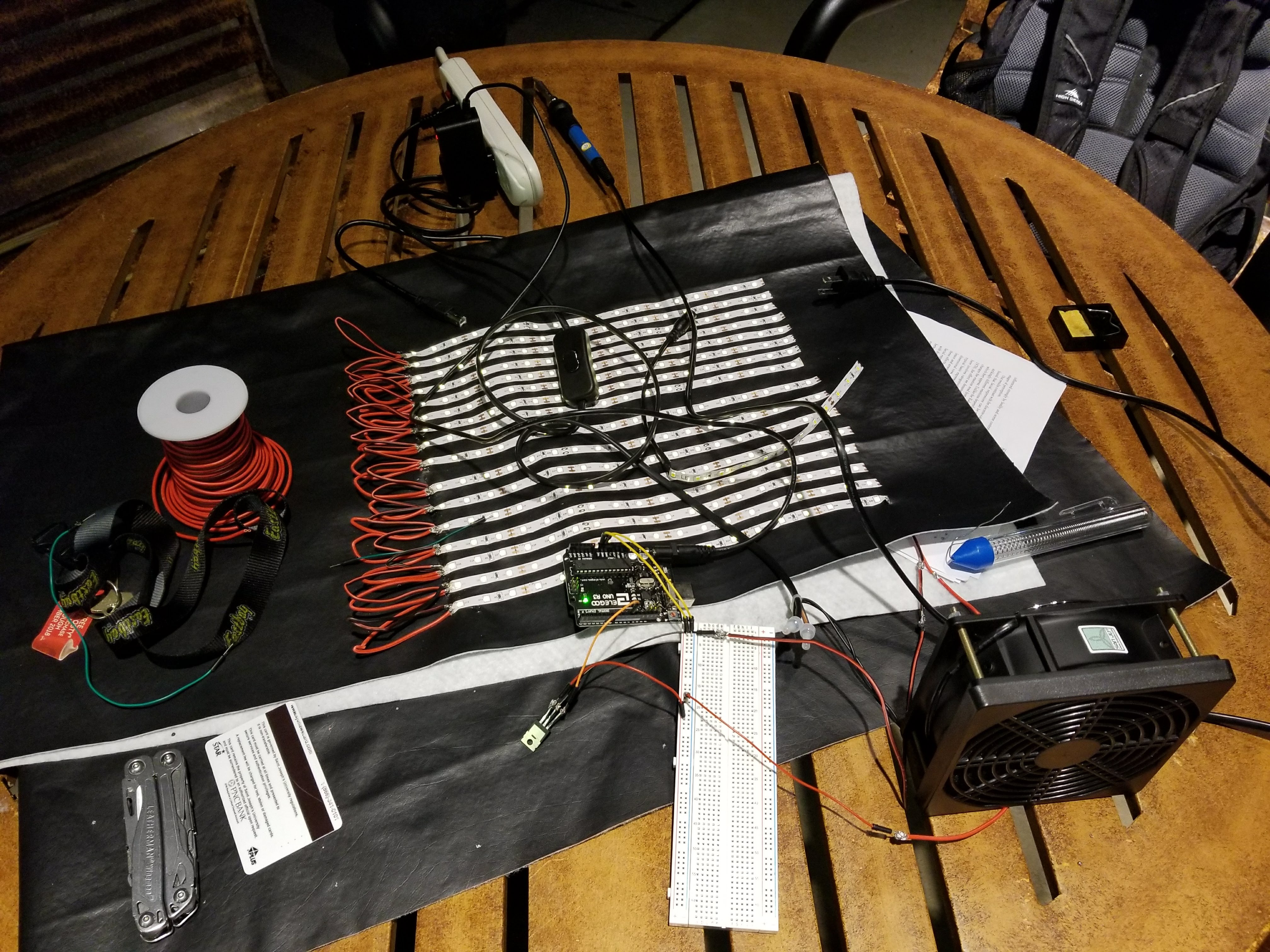
After gathering all the parts, I got down to work!
First Things First
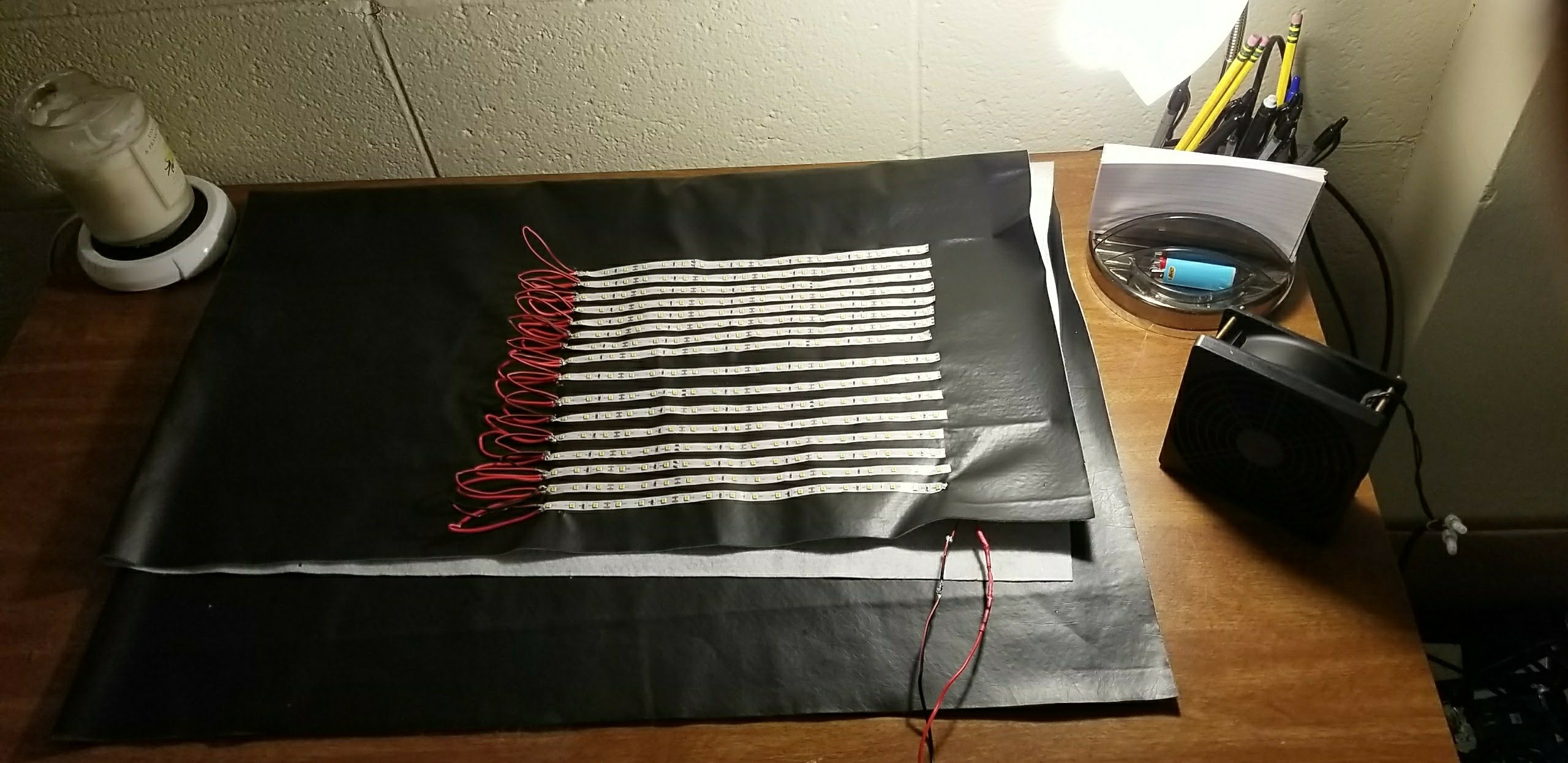
I wanted to make my panel rectangular so that when the light shines at 7 in the morning, it would cover my entire field of vision and (hopefully) wake up. I decided to make each strip 18 LED lights long. I then cut pleather to make a lightweight, flexible panel panel.
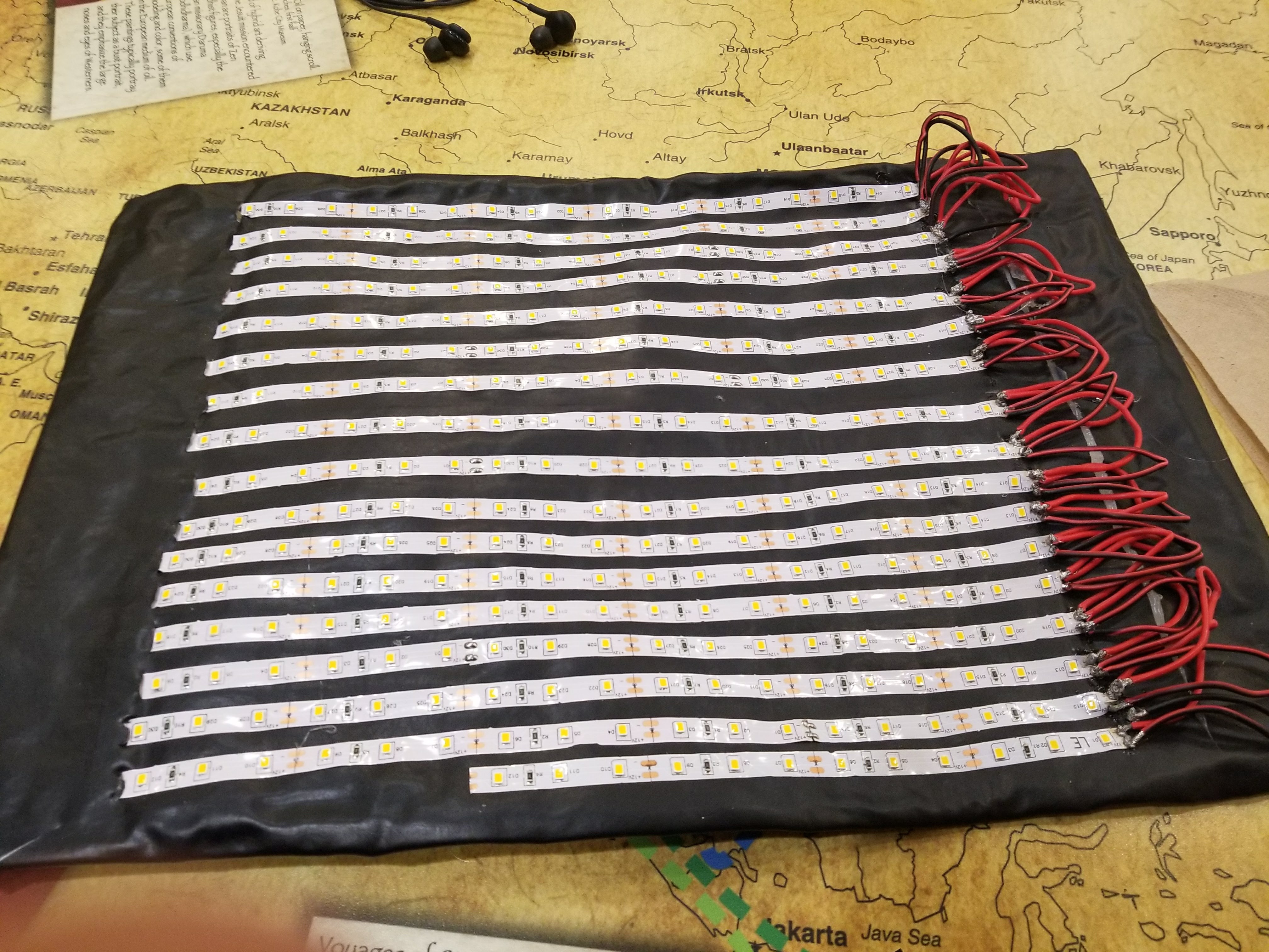
It wasn’t too long until I hit my first roadblock, which was soldering. I found the culprit, or should I say culprits. The first problem was I placed the LED light strips too close together. Originally this was what I wanted so that when the lights turned on, the concentration of light would be very bright as opposed to having the strips widely dispersed in a way that the concentration of light would be weak. Having the LED strips and wires so close together caused the red and black wires to touch in some instances and cut the electric circuit short. The end result was that only some LED strips remained lit and those that did usually flickered.
The second issue was the red and black wires were too stiff and wouldn’t stay bent since the I was bending them too sharply. This caused the thick wires to literally rip the soldering wire metal off of the LED light panels, cutting the circuit short.
I rearranged space between the strips so that 1) soldering the wires together became much easier, 2) the positive and negative wires wouldn’t touch and accidentally cut the circuit short, 3) bending the positive and negative wires wouldn’t be under enough stress to rip the metal off the strips again and 4) to provide a larger area of light output while making sure the light output was strong enough to wake me up.
Let There Be Light!
I held my breath while I plugged the power supply into the socket… and it worked! Or at least the first three rows. The positive and negative wires were soldered together on the fourth row by accident that cut the circuit short. Whoops. After resoldering, everything worked perfectly.
My next step was to add the aluminum wire to the panel. This would allow the flimsy panel to hold its form when manipulating it. This was accomplished by cutting the wire slightly shorted than the perimeter of the panel. I then used a hot glue gun to make the aluminum wires stayed put. Lastly, I folded the fake leather over aluminum wire so that it was hidden. Again, I used a hot glue gun to keep this leather down so that the wiring would remain concealed.
I then made slits where the strips ended on the opposite end of where the soldering of wires was done. This helped hide where the positive and negative ends were exposed. I also made a small cut where the power adapter was and threaded the power adapter through the hole so that it would remain hidden from the front view.
After testing out the lights one last time to ensure that everything was working, I switched over to the software side of things.
A Simple Microcontroller for a Simple Task: Arduino Uno
Keeping my costs down was my number one priority. Originally, I thougt about using an STM32 but I already had a spare Arduino Uno laying around so I thought it was about time putting it to use. I had also considered using an Arduino Mega2560 as well but thought it would be a little bit overkill since has more I/O pins than I know what to do with and more horsepower necessary for this particular project.
Programming it was straightforward. I needed to get acquainted with two libraries: TimeLib & TimeAlarms. TimeLib is used for timekeeping functionality, which would help me keep track of the time that has passed between each day. TimeAlarms would allow the Arduino to do a specific task based on what time it is. The documentation for each respective library was straightforward and easy to follow. Along with Adafruit’s guide on LED strips, I was able to write up a relatively simple program below:
#include <TimeLib.h>
#include <TimeAlarms.h>

#define PIN 10            // control pin
#define DELAY 10          // 20ms internal delay; increase for slower fades

int long countDown = 1800 * 1000;

void setup() {

  pinMode(PIN, OUTPUT);

  // Setting time format (24 hour):
  // HOUR, MINS, SECS, MONTH, DAY, YEAR (20XX)
  setTime(00, 13, 00, 3, 1, 18);

  // Setting up when the alarm should go off
  Alarm.alarmRepeat(6, 45, 00, fade);
}

void loop() {
  Alarm.delay(1000); // wait one second between clock display
}

void fade() {

while(countDown != 0){

  delay(1000);
    // fade in
    for(int i=0; i< 255; i++) {
      analogWrite(PIN, i);
      delay(DELAY);
    }

    // fade out
    for(int i=0; i< 255; i++) {
      analogWrite(PIN, 255 - i);
      delay(DELAY);
    }

    countDown -= 5000;
  }

  countDown = 2700 * 1000;
  analogWrite(PIN, LOW);
}
Piecing Things Together
My next step was bringing the project together. I connected pin 9 (PWM) to the source of the MOSFET. It is important to use a pin with a tilde(~) next to it. These pins support pulse width modulation which allow the light to dim the LED lights by getting analog results with digital means. Of course, one can have it so that the lights turn on as bright as they can without the pulsating fading effect but I opted for these effects because I thought it would be easier to wake up to. To each their own for lighting methods!
I then connected this pin to the source terminal of the MOSFET by soldering the ends together using some soldering wire. This was a little tedious since I had to solder outside (no soldering allowed in the residence hall) in 40° weather where the soldering wire was reluctant to melt and was even more reluctant keep this composition while I managed to merge the two ends together. After more attempts than I would like to admit, I finally got it.
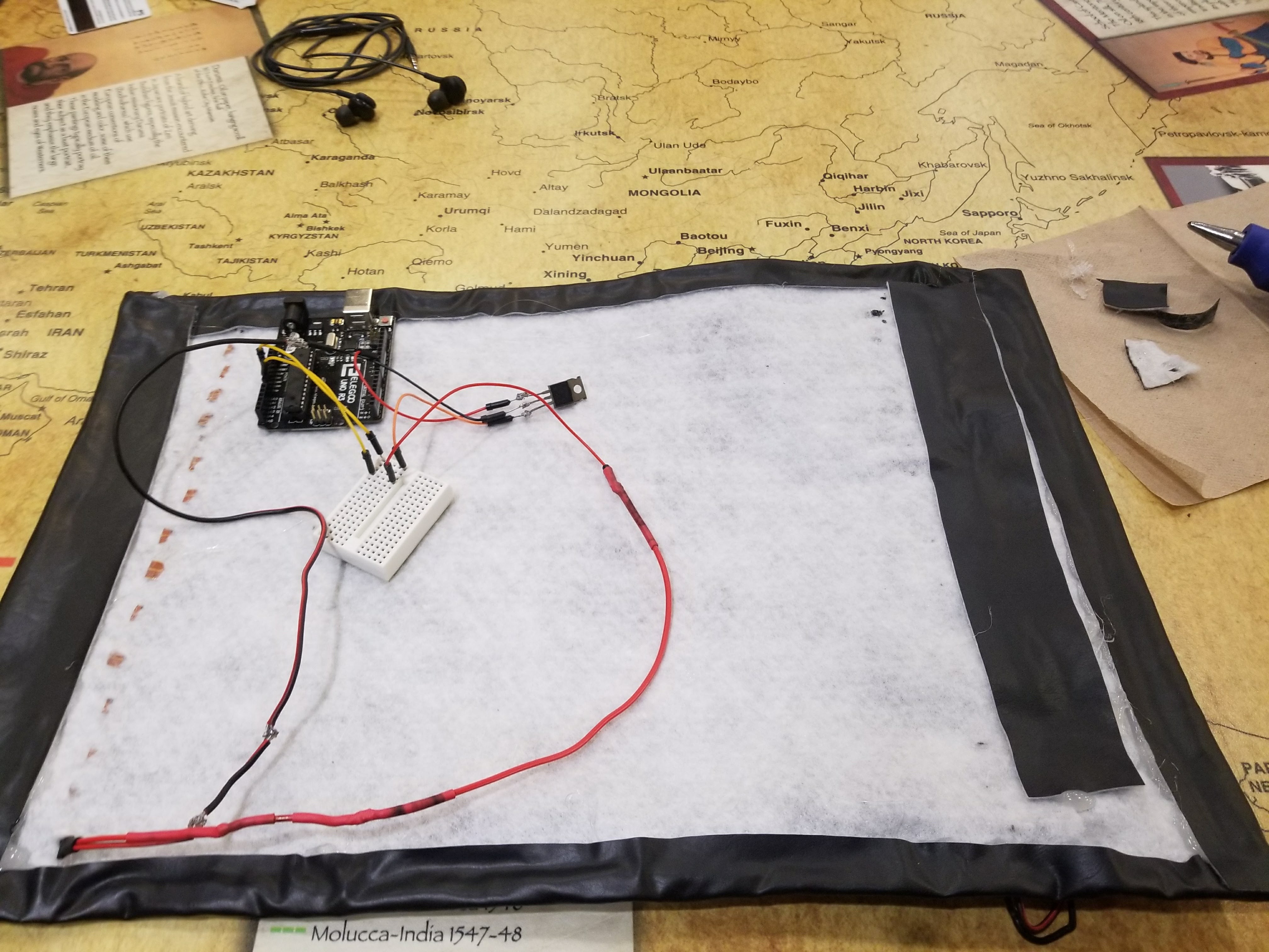
Next I decided to solder the gate terminal to a jumper wire connected to negative wire that directly fed into the negative end of the LED lights. I then connected drain terminal to the GND pin on the Arduino. Lastly, I connected the positive red wire from the LED strip to the VIN pin which powers the panel with 9V of electricity.
Tying Up the Loose Ends
From a functional stand point, my product worked and was 100% complete. Structurally speaking, there was still work left to be done. I wanted to suspend my LED panel above my bed but initially had no clear way of doing it so I eventually decided to create loops out of my pleather that I would thread with some cheap string. I held down the loops using my hot glue gun and was able to suspend it all with string that was connected to a nail above my bed.
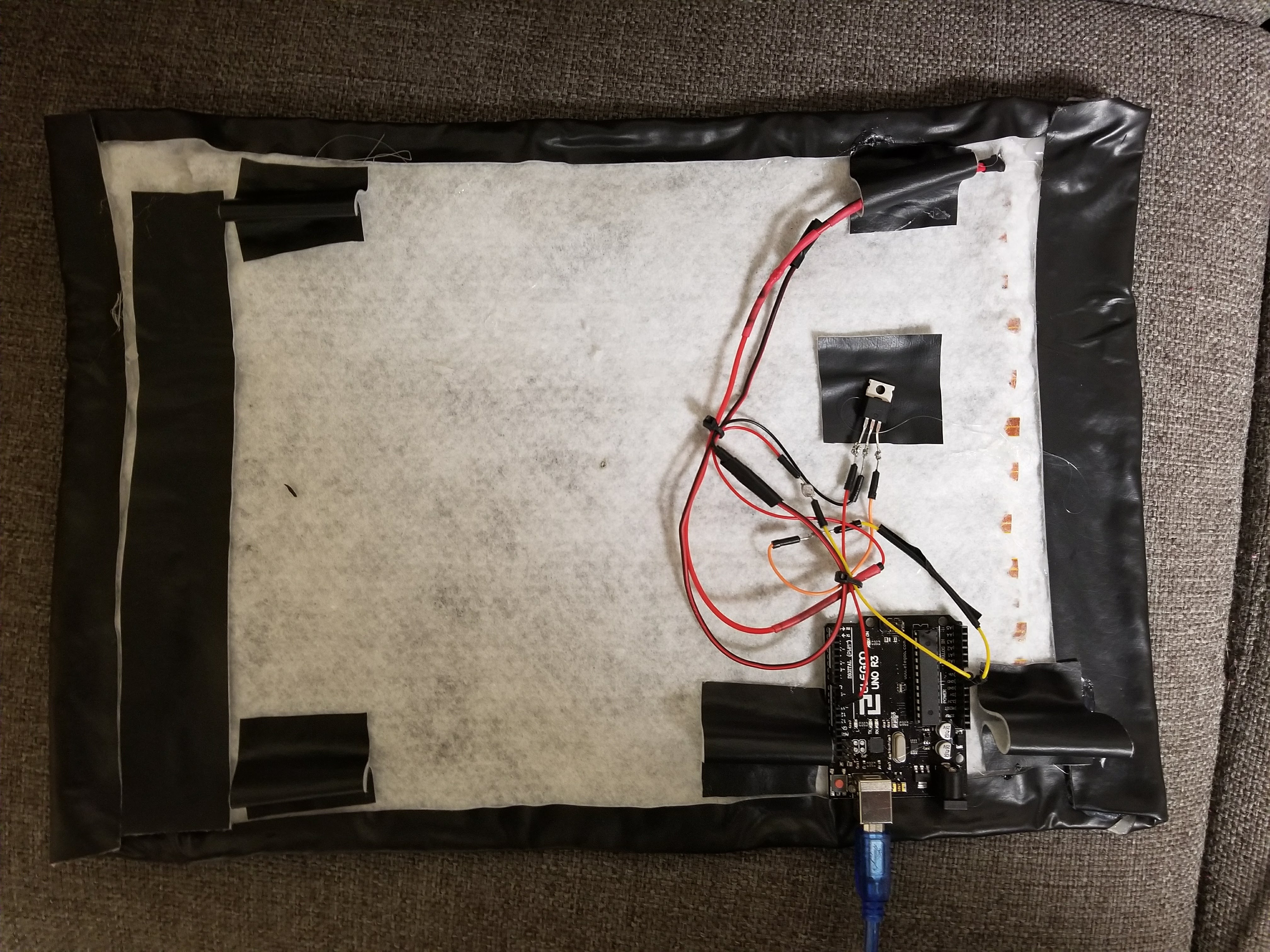
My wiring was a little hectic so I decided to use zip ties to organize them better. I then glued my Arduino to the back of the LED panel so it was out of sight and securely attached to the back side that you can see in the picture above.
Conclusion
Overall, I learned a lot through this project. I had recently began looking for ways in my own life to solve any problems I might have through technology and I accomplished my goal. I explored two new and very practical libraries that may come handy somewhere down the line and I few like I have a pretty solid understanding of basic electronics. Now waking up isn’t so bad and I won’t be sleeping in anymore 8 am classes, at least I hope not!